Nuvera Fuel Cells: Cell Component FEA & CFD Analysis
Background
Nuvera Fuel Cells manufactures heavy-duty, zero-emission hydrogen fuel cell engines, which convert hydrogen gas and oxygen into electricity through an electrochemical process. The hydrogen is split into protons and electrons, and the protons combine with oxygen while the electrons pass through a circuit, generating electricity and water as the sole byproduct. This occurs in fuel cell stacks - made up of singular fuel cells - shown zoomed in on the right.
During use, fuel cells become compressed to ensure good thermal and electrical conductivity, so I was tasked with simulating the compression to varying thickness, simulating the flow of air through the channels (from green to blue), and analyze the resulting pressure drop.

Objectives, Constraints, & Skills Applied
Objectives
-
Conduct an FEA on the original fuel cell model to compress it down to 3 desired thicknesses
-
Take the deformed models and conduct CFD analyses to measure the pressure drop of air within the models
Constraints
-
The FEA and CFD must use a reasonable amount of solve time and computational power
-
The deformed model must maintain the same horizontal dimensions as the compressed cell
-
The deformed model must also be airtight for accurate pressure drop results
Skills Applied
-
SolidWorks 3D Modeling
-
SolidWorks Simulation (FEA)
-
SolidWorks Flow Simulation (CFD)
Conducting the FEA
Running the entire fuel cell package would require too much time and computational power, so only a fraction gets run and the results are stitched back together.
Slicing the "Header"


The term header is used to describe the area within the cell in which the fluid enters and exits. The fluid also passes though a large open area, as seen in the figure above, sandwiched between the 2 headers. The sliced part on the far left represents the smallest repeating unit in the header, with the circled region showing where the fluid travels. Next to it shows an areal view of the sliced part. Note that the channel was sliced in half to reduce part size since it is symmetrical.
Now that the majority of the fluid volume is accounted for, all that needs to be sliced is the actual entry and exist, shown to the right. The parts here also are sliced vertically to reduce size since the resulting model can be mirrored at that same plane.


Running FEA & Stitching Headers Together

The goal is to compress the model down to varying lengths, so once that is accomplished with the FEA, only the volume in which the fluid travels is crucial for the CFD analysis. This means that any other components can be hidden except that volume, which is circled in black.
Using the original, non-deformed model, the part on the left is created from the results above. It keeps the exact shape of the interior fluid flow cavity while cleaning up the exterior by removing extra material. This structure's dimensions were chosen so that it can be repeated for every channel the header has, making the total header dimensions aaccurate. It is also important to note that the inlet and outlet use the same header.
The next step is modelling half of the inlet (again since it is symmetrical) using the repeating units above. Each header has 6 channels, so 3 units are stitched together. However, since the inlet/outlet attaches to one of the units, a cavity has to be carved out for that part to fit. In this case, a cavity with the exact dimensions for the inlet is created, so that when added, this model retains correct dimensions as the original model.


Once the FEA for inlet/outlet is run and modified to remove unnecessary features, it gets stitched to the cavity as shown above. Borders are added all along the edges of the model to make sure it is watertight, which is crucial for the CFD study, so the goal is to make this one cohesive part. The FEA will result in a lot of complicated geometries, so much of this project was focused on manipulating the deformed results and being able to stitch them all together to create this watertight model without sacrificing dimensional accuracy. The figure above to the right shows the inlet header (as seen with the larger opening) completely put together with 6 channels. The same process is replicated with the outlet header to have 2 total. This entire process is then repeated for every desired thickness.
Connecting Headers Together
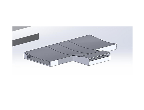
After the 2 headers are created, the open area between them is added. It only consists of 2 parts, enclosed with a watertight border: a mesh-like material modeled by a rectangular prism and a dimple plate added from the original model. The mesh material will be assigned a porous media in the CFD to replicate the qualities of a fluid passing through it. The detailed view shows the porous media, and it lines up directly with the 6 channels so the fluid can pass in and out of it. The fluid passes through the mesh, along the dimple plate, which causes the pressure drop. When all the components are put together, the final model below is created; it consists of 2 solid bodies with the porous media intentionally not combined with the rest of the model so that certain properties can be applied to it.


CFD Analysis & Collecting Results
Once a full model is created for the desired thickness, the fluid and porous media properties are added to calculate the pressure drop across the part.
The last step of this process is conducting the CFD analysis to find the pressure drop. There are 2 independent variables in this study - the fluid mass flow rate and the properties of the mesh - so parametric studies was used, where data could be collected at multiple flow rates and porous media conditions. On the right shows the computational domain, where only half of the model ran the CFD - another effort to decrease solve time due to the symmetrical geometry. In terms of data collection, there were 4 locations at which the pressure was recorded: the inlet face, the plane where the inlet channels meet the mesh, the plane where the mesh meets the outlet channels, and the outlet face. This will provide data on how much pressure is lost at each model section.
