Toast: Instron Device Torque Measurement Fixture
Background
The Toast Flex terminal is a countertop device used by restaurants process orders and payments worldwide. A key feature is the hinge that allows users to tilt the screen to their comfort level, so determining exact hinge torque measurements were necessary for the development of the next generation of products.
At first - as shown on the right - measurements were taken with a handheld force gauge, where there was a high room for error in making the moment arm and force perpendicular as well as an uneven force application on the device. To get the most accurate measurements, I was tasked with developing a fixture so that an Instron would be able to both apply and record torques on the hinge.

Objectives, Constraints, & Skills Applied
Objectives
-
Design a vertical device base mount in which the hinge lies in the Instron axis of rotation
-
Design a compatible Instron attachment to apply and record the torque to the screen's surface
Constraints
-
The mount must be attachable to an Instron component test plate containing an array of M6 through holes
-
The mount must be able to satisfy device placement along any location on the X-Y axis of the plate
-
The devices base should be tightly clamped to the plate, and clamps must accommodate for any base thickness
-
The Instron attachment should account for any device thickness and minimize scratches to the screen
Skills Applied
-
SolidWorks 3D Modeling
-
SolidWorks 2D Drawings
-
SolidWorks Simulation (FEA)
-
Design for Machining
-
Design for Assembly (DFA)
-
Supplier/Manufacturer Relations
Top Level Vertical Mount Design
The purpose of this mount is to fixture any device vertically, so that its hinge axis of rotation lines up with the Instron's line of rotation. This will allow the machine to accurately apply a torque on the device.

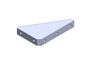
Base Plate
The base plate is a 200 mm x 150 mm x 12.5 mm slotted plate, with a purpose of fixturing the vertical mount and the support brackets to the Instron component plate. The slots allow for precise positioning of the device along the x-axis, and the through holes on the edges give even more flexibility for positioning the vertical plate. An array of slots was chosen over identical full-length slots to allow for pockets of solid material for greater strength without sacrificing functionality.

Vertical Plate
The vertical plate is a 280 mm x 200 mm x 18.5 mm T-slotted plate, for which the base of the device sits on. The slots are used for adjustable clamps and now allows for precise positioning along the y-axis. Movement along the z-axis as also allowed, but since the axis of rotation is also along that axis, its positioning is inconsequential. Base plate attachment holes and support bracket holes are also placed one each side for plate reversibility and greater ease of use.

Support Brackets
The support brackets are added on both ends of the plates for added rigidity to the system as a whole. The M6 threaded holes are spaced evenly on both sides for attachment in either orientation, and all the ends are chamfered to prevent any fitting issues with the vertical or base plate.
Clamping Bracket & Spacers
The clamping bracket is used to fixture the device being tested to the vertical mount to align its hinge with the Instron's axis of rotation. The assembly includes the custom bracket and spacers (for increased height to accommodate devices with thicker bases) as well as OTS components, which are labelled to the right. The wing bolt also threads in and out of the hole to clamp varying base thicknesses to the vertical mount.

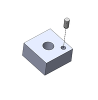
Each spacer has an M3 hole on its top and bottom surface: one is press fit and the other is clearance fit. The press fit hole has a dowel pin attached to it, while the clearance hole is used as a locating feature for another dowel pin-spacer assembly. This allows any number of spacers to be stacked up while maintaining uniformity on all sides. The bottom of the clamping bracket also has a clearance hole for its adjacent spacer.

Clamping Bracket Design Flow


The initial design consisted of an L-shaped bracket in which the top of the clearance hole sat in the same plane as the top of the threaded hole. This, however led to 2 issues: the space under the overhang was very limited especially with the height of the swivel mount, and there was a large stress concentration due to how long the overhang had to be.
The second iteration included a "step" design in which the threaded hole was raised above the T-slot hole for increased height below the overhang. However, there was still a large stress concentration due to the thickness of the "step".
The final design was able to drastically reduce the stress concentrations by adding more material in the clamp. This design also allows for maximum height and area under the overhang for the swivel mount.
Top Level Rotating Attachement Design
The purpose of this attachment is to to be able to apply and record the torque on the device. 2 of these assemblies must be machined, one that attaches to the top Instron load cell and one to the bottom, and both clamp to the device's screen.

Instron Load Cell Interface
The Instron load cell interface inserts directly into a slot located in the load cell. The M6 hole fits a clevis pin to lock the interfacing piece into the Instron, and the M15 external threads below are used by the lock nut to stabilize the attachment. The original design consisted of this interface and the clamping bar (shown below) machined as one piece, but due to geometric complexity it was split into 2. Under this interface lies a threaded M6 hole for a screw to attach both pieces together.

Rotating Clamping Bar
The rotating clamping bar is a 200 mm x 30 mm x 15 mm attachment that functions to clamp any devices surface and apply the necessary torque. On each side of the bar lies 4 symmetrical M6 threaded holes for the clamps, so the user can adjust force application location and magnitude for the device tested. In the center lies a cutout for the load cell interface shown above with a counterbored M6 holes underneath, again to fixture the pieces together.

Intron Load Cell Interface Lock Nut
The locknut is used to tighten the attachment to the Instron to prevent any slipping or stability issues that would corrupt the data. In the center lies an M15 threaded hole, and the sides have M6 holes in which extra force can be applied to tighten the nut even further.

Device Clamps
A threaded bumper was chosen to act as the clamping mechanism, which has a steel internal base for strong engagement with the wing bolt, but a soft rubber exterior for contact with the device screen to prevent surface scratches. The wing bolt threads into any of the holes in the rotating bar, and the bumper screws into the bottom of the bolt.

Results


Design
Functionality
Once the machined parts and OTS components arrived, the fixture was assembled and all the parts fit together as expected. Different devices were tested for stability, and the versatility of the fixture allowed for each to be aligned properly for testing. Since the parts had arrived after my coop was completed, I was unable to conduct any of the testing, but the company plans on using the fixture for all future hinge torque measurements.
